Your backhoe loader handles a wide range of tasks, enabling you to handle heavy materials & perform challenging tasks like digging & trenching. Have you ever wondered how it lifts tons of steel & enables you to effortlessly manoeuvre it with just one hand? We often laud a backhoe loader machine’s versatility, but often forget the significance of a backhoe steering system.
The steering system bridges the crucial gap between an operator’s intent & the machine’s movement. Unlike transport vehicles, which use a rack & pinion steering system, construction machinery uses a steering system that operates through a hydraulic system, designed for heavy-duty applications. So how do they work & what are the components?
In this blog, we’ll discuss how steering systems in backhoes work, the components & maintenance tips.
Backhoe Steering System: Overview
The backhoe steering system is designed to manoeuvre a backhoe loader machine while it is digging, loading & transporting at sites. The steering system consists of a hydraulic circuit that’s designed to multiply torque. When the operator provides a small amount of input force (via the steering wheel), the system amplifies it to articulate the wheels.
In challenging situations like terrain & tight urban environments, the precision offered by a backhoe’s steering system is vital. Whether you’re navigating a construction site or loading materials from a dump truck, the steering needs to be responsive.
Most modern backhoes use a hydrostatic or a power steering system, meaning there is no mechanical linkage between the steering column & wheels. Instead, both system uses hydraulic lines to convey the response from the steering wheel to the axle. This makes it easier for the operator to turn the wheels as the hydraulic fluid & pressure do the work, not your shoulders.
Components Of A Backhoe Loader Machine Steering System
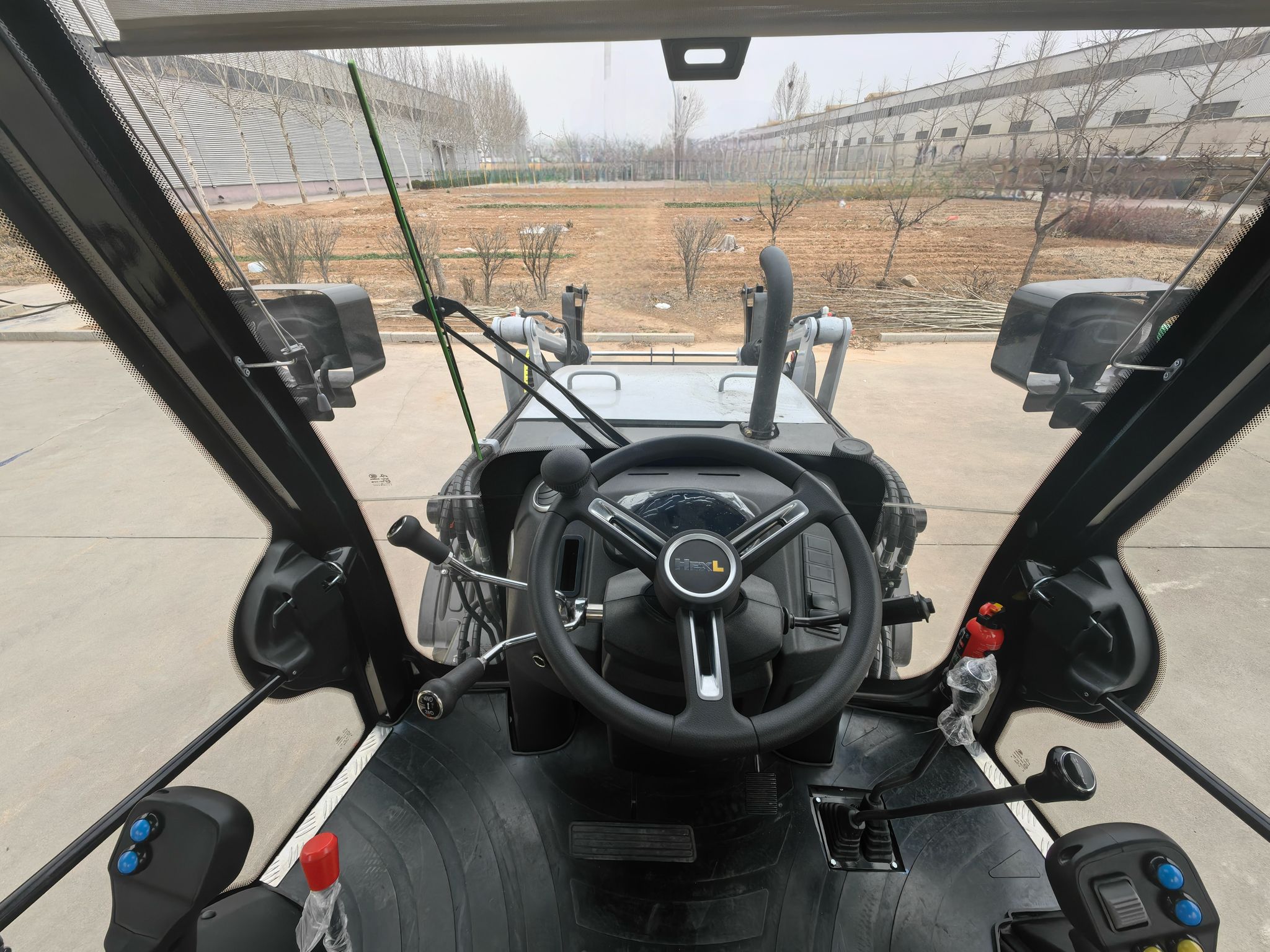
1. Steering Column & Wheel: Acts as the interface for the operator, translating hand movements into steering commands.
2. Hydraulic Pump & Cylinders: The hydraulic pump is the heart of the hydraulic system, which pressurises & pumps the fluid flowing through cylinders that move the wheels.
3. Linkages & Control Valves: Linkages regulate & direct the flow of fluid through the correct cylinders, offering precise wheel movement. Control valves are like traffic controllers, responsible for deciding the amount & direction of fluid.
4. Tyres & Axles: The tyres & axles are responsible for translating the vehicle according to cylinder movements, reinforced to handle heavy loads & rough terrain faced by construction machinery.
5. Drivelines: Construction machinery, like backhoes, is available in two driveline choices: 2WD or 4WD. Models offering 2WD are more affordable & consume less fuel, but offer less grip. On the contrary, 4WD models, while costlier & consume more fuel, deliver better traction on rough & slippery surfaces.
Step-by-Step Working Of A Backhoe Steering System
Once you’re inside the backhoe cab & start the engine, the hydraulic pump begins circulating the hydraulic fluid. Here is what happens when you command the backhoe loader machine to turn:
1. Steering Input: When you rotate the steering wheel on either side, the rotation is conveyed down from the steering wheel to a control unit, called the Steering Control Unit (SCU).
2. Hydraulic Pressure Activation: When the SCU opens specific ports, it measures & adjusts the flow of the hydraulic fluid and sends it to the right or left turn line.
3. Actuation: When the pressurised fluid enters the hydraulic steering cylinder, the pressure pushes against the internal piston.
4. Displacement: As pressure builds up against the internal piston, the cylinder rod extends, pushing the steering knuckle to the axle. Simultaneously, the fluid on the other side is sent back to the reservoir.
5. Movement: The force applied to the knuckle turns the wheel assembly. A few pounds of force on the steering wheel translates to thousands of pounds of force on the axle, all because of the hydraulic advantage.